
Safety and Ethernet.
Problem statement.
An industrial plant, such as a processing plant or a manufacturing plant, conceals hazards and sources of accidents. This presents a risk to safety. The greater the potential hazards to life, environment or property, the greater the number of measures required in order to reduce the risks to a minimum.
Protective equipment is designed to control these hazards or to reduce these hazards to an acceptable minimum.
Therefore, protective equipment is primarily used to prevent events or plant conditions, which could result in personal injury or environmental damage, and also to prevent damage to plants or machines, which could result in production downtimes or loss of value.
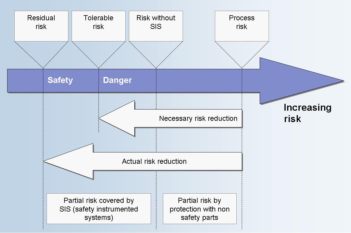
The risk.
The risks posed by an industrial plant must be reduced to an acceptable minimum.
Protective measures include a safe plant design, technical safety, primary protective measures such as protective barriers or safety valves, administrative measures and, above all, control and instrumentation technology equipment, such as safety controllers.
Standardisation.
Over the last 100 years, a wide range of regulations and standards have been established to keep pace with the development of technology. One of the best known safety standards is DIN VDE 0116, "Electrical Equipment Of Furnaces (draft standard EN 50156). This standard contained definitions relating to the design and behaviour of burner controls for gas and oil burners. It also served as the basis for the TRD (German Technical Rules for Boilers).
In 1984, TUV Rheinland and TUV Bavaria published the book "Mikrocomputer in der Sicherheitstechnik (Microcomputers in Safety Technique, 1997) due to the increasing use of microcomputers in safety-related systems. The then-existing standards were classified into five safety classes (SC) based on the severity of their requirements and measures were introduced for the use of microcomputers in safety technology. Safety class 1 was the highest classification grade and safety class 5 the lowest classification grade. This application-dependent classification meant, for example, that press controls were classified into safety class 1 and burner controls into safety class 3. Today, the classification into safety classes based on the TUV book is not relevant and was not incorporated into a standard.
1990 saw the publication of DIN V 19250 (Basic Safety Considerations for Control and Instrumentation Technology Equipment), which describes processes for an application-independent class classification based on a basic risk assessment according to DIN 31000 (General Guidelines for the Safety Design of Technical Products). This resulted in a classification into eight requirement classes (RC), with RC 8 representing the class with the highest requirements and RC 1 the class with the lowest requirements. This standard was extended by DIN V VDE 0801 "Principles for Computers in Systems with Safety Tasks", which describes possible measures in safe computer systems based on the requirement classes.
The verification of the system's functionality was thus ensured with a certification according to DIN V 19250 and DIN V VDE 0801.
The now Europe-wide accepted safety standard IEC 61508 is designed to provide the missing quantitative verification (assessment of the remaining risk).
In August 2002, safety standard IEC 61508 was published as EN 61508. Currently, this standard is being adopted by the DKE (German Commission for Electrical, Electronic & Information Technologies of DIN and VDE) into the German set of standard specifications as DIN EN 61508 (VDE 0803). Any conflicting national CENELEC or CEN standards must be withdrawn by August 2004.
Together with IEC 61131-2, IEC 61508 forms the basis for the manufacturer and for the certification of electrical/electronic/programmable electronic-based safety-related systems (E/E/PES).
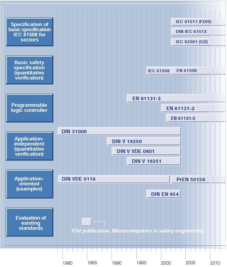
Currently, application-specific standards are in planning on the basis of safety standard IEC 61508, such as IEC 61511 (application of IEC 61508 in the process industry), IEC 61513 (nuclear industry) and IEC 62061 (manufacturing industry).
These application standards, which are important to planners and operators, are also being adopted as EN 61511 or DIN EN 61511 into the European and German set of standard specifications.
Here, a distinction is made between systems with demand mode operation (protection systems similar to VDI/VDE Directive 2180) and systems with uninterrupted demand mode operation (continuously working systems that control and regulate the process).
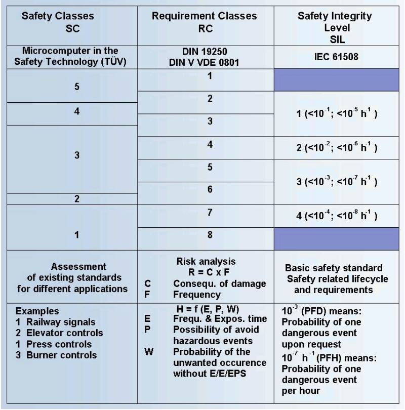
Instead of the eight requirement classes based on DIN V 19250, the safety-related SIL (Safety Integrity Levels) classification grades 1...4 are used for IEC 61508. The risk assessment for determining RC or SIL is conducted via a risk graph with the same criteria. For every SIL grade, a failure probability is defined as PFH (Probability of Failure per Hour) or PFD (Probability of Failure on Demand). It is defined for every safety-related loop (that is, from the sensor via the control unit to the final control element) and must be verified.
The probability of a dangerous failure is determined for the individual modules or channels of a PES by means of failure tree analyses and Markov models. These failure analyses are also the basis for the certification of a safety-related PES for an independent inspection authority such as TUV and BIA.
The definition of the different types of failure is the basis for the failure analysis.
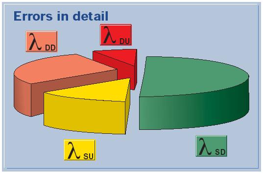
A safe detected failure rate (Lambda SD), a safe undetected failure rate (Lambda SU) as well as a dangerous detected failure rate (Lambda DD) are unproblematic.
The dangerous undetected failure rates (Lambda DU) are problematic and must be reduced to a tolerable remaining risk.
The main problem is in the sensor and actuator circuit. Unfortunately there are (still) not enough statistical statements on the failure behaviour of these elements - similar to the failure rate of electronic components. This fact is also considered in IEC 61508. Analysis indicates that the logic unit is involved with 15 % in the probability of a dangerous failure of a de-energising circuit, and the sensors and output circuit elements with 35 % and 50 %, respectively. If this applies in individual cases, the failure setpoint for SIL 3 for a logic unit must be smaller than or equal to 1.5 x 10⁻⁸ h-1.
A safety-related measurement and control loop (safety loop) consists of the sensors, the transmission for safety-related entry, the safety-related communication for processing, followed by the safety-related communication for execution and the transmission to the actuators.

As shown in the model, the safety-related communication is a major part of the safety system.
This communication is to be given greater emphasis in the safety system in the future. A decentralised plant automation system allows for enormous savings to be made in the wiring and required space.
Like every component of the safety system, the safety-related communication must also meet the relevant safety standards.
The failure control.
During the safety-related transmission of messages, the definitions and standardisations which have already been defined for fieldbus technology can also be used as a basis of communication for "Industrial Ethernet.
NAMUR recommendation NE 31 and VDI/VDE Directive 2180 require that the safety-relevant and non safety-relevant facilities are separated in terms of hardware. However, bus and network technologies allow the common use of protective functions and operating functions. It must, however, be ensured that the protocol level is uniquely separated.
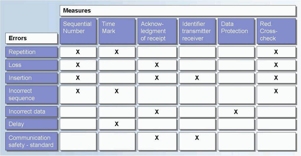
According to NAMUR recommendation NE 97, in the case of safety buses the following "failures must be identified within the failure tolerance time and a corresponding safety-related response must be triggered":
- Corrupted addresses- Repetition
- Loss
- Insertion
- Incorrect sequence
- Corruption of information
- Delay
The FAET draft also describes the possible failures of a "bus system for the transmission of safety-relevant messages". In addition, the proposal defines individual measures in order to exclude the corresponding failures.
However, in the case of a safety-related data transmission, not only functional requirements and quantitative measures must be considered, quantitative verification must also be provided.
Causes, which lead to transmission failures, must be considered, failure control measures, failure recognition and failure correction must be carried out. The corresponding remaining failure probabilities must verified. In IEC 61508, total failure probabilities are considered based on a quantitative model.
In this case, as a rule of thumb, the bus system is responsible for 1% of the failure probability of the provided safety function. In other words, in the case of an application according to IEC 61508, which should meet requirement grade SIL 3, the failure setpoint of the bus system must be smaller than or equal to 1 x 10⁻⁹ h-1 (1 % of 1 x 10⁻⁷ h-1).
The bus system must be provided with different measures for preventing failures for all types of failure and have a total remaining failure probability that is smaller than or equal to 1 x 10⁻⁹ h-1. An example of a measure against a corrupted message is the creation of a CRC with 32 check bits, which has remaining failure probability that is smaller than or equal to 2.23 x 10⁻¹⁰ h-1 with a maximum of one transmission per ms.
Ethernet for safety-related transmission.
The problems with Ethernet.
The CSMA/CD access method is based on a segment with collisions. Consequently, it is not possible to make any definitive statements on runtimes.
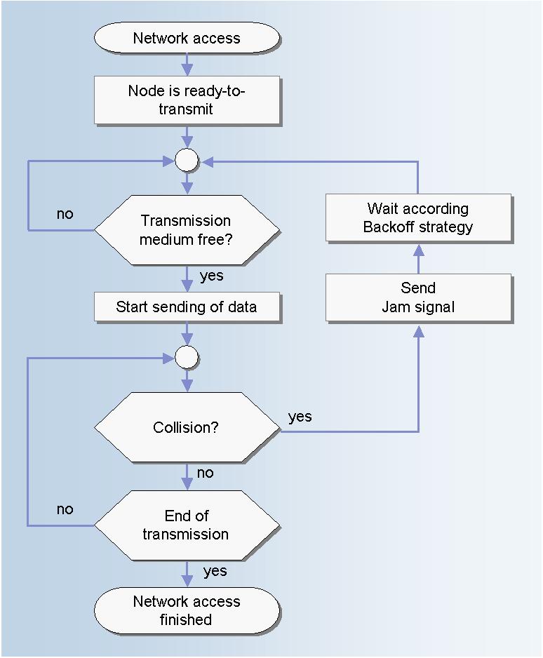
Thus, deterministic or correct sequential transmission with Ethernet cannot take place in a collision domain. However, for the required failure control of a safety-related transmission, measures have to be taken, which are in conflict to the restrictions in a collision domain in the Ethernet.
Depending on the application, different response times and thus also corresponding safety times are required. That extends to the real-time capability of the Ethernet network.
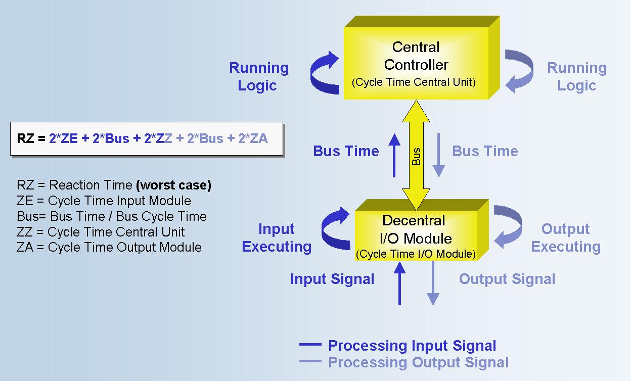
In the case of distributed systems, the response time consists of the cycle time of the processing controller and corresponding bus cycle times. During the calculation of the worst case response time of a distributed system, the bus runtime with factor 4 is included. This underlines the demand for a fast bus concept.
Applications such as press controls demand response times of a maximum of 20 ms. The safety system must now ensure that a safety-related processing including a safety-related transmission is ensured within this time, even if there are collisions on the network. In addition, all failure-controlling measures must be considered in parallel.
Switched full-duplex Ethernet networks can already meet these high requirements.
Pipelines are another application where safety and a high level of communication is required. Here, response times within seconds are accepted, for example. It must be recognised that this requirement can implement an Ethernet network with an average and a high network load.
Regarding all these considerations, it must be stated that it never involves a reduction or violation of the safety requirements. The safety-related complete system with corresponding failure control and diagnostics implements the safety function without restrictions at all times.
The considerations merely involve an assessment and project planning of the system availability.
In addition to the hard requirements to meet corresponding response times, the bus system has to increasingly meet the demand to transmit large amounts of data in the scope of safety-related transmission. Ethernet is also the suitable transmission method for this demand.
The solutions.
Different organisations and corporate mergers are currently working on developing safety-related data transmission options via Ethernet. This includes the IDA, which is a member of the independent umbrella organisation IAONA.
Others names include Rockwell as well as the organisation ODVA with Ethernet IP (DeviceNet Safety) and Siemens with the organisation PNO with ProfiNet (PROFISafe).
Vendor-specific solutions are already available for a safe Ethernet.
The Bibliography.
IEC 61508, Part 1 to 7;
FAET Technical Committee for electrical engineering, final draft "Bus Systems for the Transmission of Safety-Relevant Messages;
NAMUR NE 97, Fieldbus for Safety-Related Tasks;
Reinert D., Schфfer M. (Editor), Safe Bus Systems for Automation, Huethig;
Boercsoek J., Networks in industrial Applications, VDE Publishing House;
Hirschmann Electronics GmbH & Co KG, Basics of Ethernet and TCP/IP.
Here you can find some more information about safety and risk.
www.risknowlogy.com
Some Questions to ask a Safety/Critical Control Supplier!
Safety_Questions.pdf
If you want to send us an e-mail:

Franz Handermann
Viehtrift 29
67346 Speyer
Germany